
Automotive climate control panels & display check.
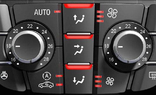
In an assembly plant, 20 variants of car climate control panels are assembled and the symbols are lasered. For the laser engraving of the symbolism, the black painted aperture parts must be positioned very precisely. By removing the paint, the symbols of the opaque white base body appear and can be recognized by the driver with backlighting, even at night. The extensive machine vision required must measure the position of each symbol in relation to a reference point and check the quality of the characters - this takes place on a rotary table with several stations. The individual functional segments of the aperture are each examined with one camera, so that three high-resolution cameras are used on the CV-600 PC system with freely configurable software. Due to the high resolution cameras, laser errors can be detected from as little as 0.15mm Ø. The measuring accuracy of the position is 0.05mm.
The checks run automatically. The transmitted and reflected light illuminations are switched accordingly by the system at each control step. No defective parts are further assembled by the machine vision. The reject costs of the complete part with assembled electronics are reduced and return deliveries are avoided. Process faults are detected early and can be eliminated immediately, even before serial faults occur.
Completeness check of heat shield components.
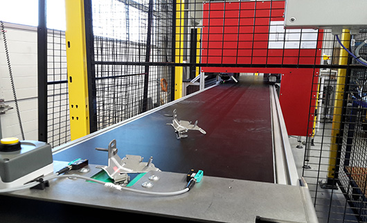
The fully automatic inspection for heat shield components is carried out with the PC-based machine vision system CV-600 based on our system software CV_Inspect. For the application, 2 camera views are required to check the complete and correct assembly and the correct geometry. The heat shield components are placed manually on a conveyor belt. The conveyor belt automatically cycles one cycle at a time and transports the components into the standard test cell with the two cameras and lighting. Once the part has reached the target position, image acquisition is triggered via Profinet. The cameras look at a specific component view in order to be able to measure and inspect as many attachments as possible. The image acquisition is stationary, the results of the test are immediately transmitted to the machine PLC and the IO component is marked by laser marking. NIO parts are rejected and not marked.
Each of the cameras locates the component in its image section, tracks its position and checks the presence of the attached parts. In addition, several measurements are carried out, especially for the position-critical attachments, so that the 3D position of these attachments can also be indirectly recorded. This enables the detection of bends or deformations and ensures smooth further processing. With the high camera resolution, even small features can be reliably inspected. The inspection characteristics are parameterized or learned. Extensive statistical functions facilitate correct parameterization. The inspection area is covered accordingly so that the feeding and continuation of parts is guaranteed, but at the same time an external light barrier is provided.
Assembly check on brakes.
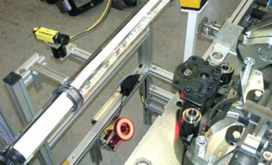
In the production of truck brake calipers a 100% final inspection should be integrated in the production line. Here the presence and correct position of the installed parts must be checked. More than 30 variants of brake calipers are produced on the production line.
After executing the last manual work step, the operator triggers the inspection by push button. With an machine vision solution for assembly inspection based on the In-Sight 3000, a very high reliability of the inspection is achieved. The automatic brightness tracking and the inspection independent of positional variations of the component ensure a very high reliability of the system despite fluctuations in ambient brightness. During the inspection, 15 positions are checked with one camera recording: presence and correct position of screws, springs, type plates and wear indicator elements.
For this purpose, the position of a symbol and the correct number of colour markings are checked. Robust machine vision tools from our standard library and several decentralized cameras are used here. The component type is transmitted to the machine vision system via the serial interface and the corresponding inspection program is loaded. The inspection result is displayed via an indicator light and on the screen with error-related texts. With the designed user interface an occurred error can be localized quickly and the cause can be eliminated in the process.