




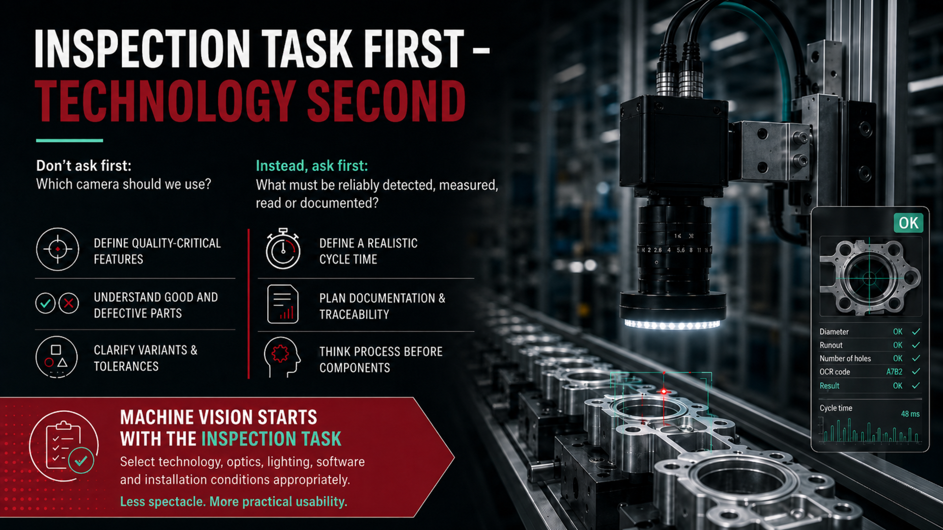
When planning a machine vision system, discussions often turn early to camera models, resolution, lenses or software. These components are important, but they are not the starting point for a robust solution.
The first and most important question is: What must be reliably detected, measured, read or documented in the actual production process?
Only once the inspection task has been clearly defined can the camera, optics, lighting, software, interfaces and installation conditions be selected appropriately. OCTUM therefore develops inspection solutions consistently from the application perspective rather than from the datasheets of individual components.
The Inspection Task Defines the System
Industrial machine vision can perform a wide range of tasks, including:
- presence and completeness checks,
- surface inspections,
- position and orientation checks,
- geometric measurements,
- OCR and OCV inspections,
- code inspection and traceability,
- print and label inspections,
- contamination inspections,
- and the detection of assembly or material defects.
Each of these tasks involves different technical requirements. A system used for presence detection may require only a clearly defined contour or strong contrast. A precise geometric measurement, on the other hand, places higher demands on resolution, calibration, product positioning and mechanical stability.
Code inspection on dry packaging material also differs fundamentally from reading a direct part marking on an oily metal component. Although a camera is used in both cases, the lighting, optics, installation position and evaluation method may be completely different.
Successful system design therefore begins with a precise description of the inspection task.
Which Feature Is Truly Critical to Quality?
At the beginning of a project, it is essential to clarify which features are relevant to product quality. Not every visible deviation is automatically a defect. Conversely, small and difficult-to-detect changes can have a major impact on function, safety or downstream processing.
Typical questions include:
- Which features must always be present?
- Which deviations affect function or durability?
- Which defects result in scrap?
- Which defects may be reworked?
- Which features only need to be documented?
- Which deviations are acceptable and which are not?
Clear prioritization prevents the inspection system from evaluating features that have little relevance to the actual quality process. At the same time, it helps ensure that critical defect types are not considered too late.
The quality objective should therefore be defined jointly by production, quality assurance, engineering and, where appropriate, other specialist departments.
Clearly Describe Good and Defective Parts
A machine vision system needs clear decision criteria. Showing only a few typical defect examples is not sufficient.
Good parts may also exhibit significant natural variation. Differences can arise from:
- different material batches,
- manufacturing tolerances,
- color and surface variations,
- changing suppliers,
- permissible process variations,
- different tools,
- or product variants.
The key question is therefore not only: “What does a defect look like?” It is equally important to ask: “How much variation is acceptable among good parts?”
If the boundary between good and defective parts is not clearly defined, the inspection system cannot make stable decisions. This applies both to conventional image processing algorithms and to machine learning methods.
A coordinated classification approach is particularly important for cosmetic defects, surface changes and subjectively assessed features.
Consider Variants at an Early Stage
Many production lines process not just one product, but numerous formats and variants. Differences may include:
- dimensions,
- colors,
- markings,
- component geometries,
- surfaces,
- assembly states,
- packaging formats,
- or different code contents.
These variants affect the design of the inspection system. Optics that provide sufficient detail for a small component may have too small a field of view for a larger variant. Lighting that produces stable contrast on a matte surface may create strong reflections on a glossy version.
The following questions should therefore be clarified during the concept phase:
- Which variants are currently being produced?
- Which formats are planned for the future?
- How are product changes performed?
- Are inspection programs selected automatically?
- Which variants can be inspected using the same image acquisition setup?
- Where are separate camera positions or lighting concepts required?
The earlier this information is available, the better a scalable and long-term system architecture can be developed.
Tolerances Must Be Measurable and Unambiguous
For geometric inspections or position checks, clear tolerance limits must be defined. Statements such as “must not be too far offset” or “should be as centered as possible” are not sufficient for automated inspection.
Clear values and references are required:
- What is the target position?
- What is the maximum permissible deviation?
- Which reference is used for the measurement?
- What measurement uncertainty is acceptable?
- How should borderline cases be handled?
- Must a single value or a complete profile be evaluated?
The required tolerance directly influences the technical design. The smaller the deviation to be detected, the greater the demands usually placed on resolution, optics, calibration and mechanical stability.
Theoretical pixel resolution alone is not enough. What matters is whether the required measurement can be performed reproducibly under real production conditions.
Evaluate Cycle Time Realistically
An inspection system must not only be reliable; it must also operate within the available production time.
The total time includes more than image evaluation alone. Factors that must be considered include:
- Positioning or detecting the product
- Triggering image acquisition
- Setting or switching the lighting
- Capturing one or more images
- Transferring and evaluating the image data
- Combining multiple inspection results
- Transmitting the result to the machine control system
- Tracking and, if necessary, rejecting the product
For very short cycle times, it may be necessary to use several cameras in parallel, acquire images while the product is moving or optimize inspection algorithms specifically for speed.
Cycle time should therefore not be viewed as an isolated figure. Product spacing, line speed, possible buffer times and the number of features to be inspected simultaneously are also important.
Include Documentation and Traceability from the Start
In many applications, a simple pass/fail signal is not enough. Inspection results must be stored, linked to production data or transferred to higher-level systems.
Possible requirements include:
- storing individual measurement values,
- documenting defect type and position,
- assigning results to a product, batch or serial number,
- storing inspection or defect images,
- logging user and parameter changes,
- transferring data to the PLC, database or MES,
- and providing information for quality assurance and audits.
These requirements affect the software architecture, storage concept, interfaces and user management. If they are defined only at the end of the project, additional effort or technical restrictions often result.
Documentation requirements therefore belong at the beginning of system planning.
The Production Process Determines Image Acquisition
Even a suitable camera will not deliver stable results if the acquisition conditions do not match the application.
Factors that must be considered include:
- position and orientation of the component,
- possible movement during acquisition,
- vibration,
- ambient light,
- contamination,
- oil mist or dust,
- changing surfaces,
- limited installation space,
- cleaning requirements,
- and mechanical accessibility.
An inspection feature may be clearly visible in the laboratory, but difficult to evaluate reliably on the production line because of reflections, shadows or fluctuating component positions.
OCTUM therefore always considers image acquisition in the real machine environment. The camera, optics and lighting are not selected in isolation, but designed together with product handling, inspection position and process conditions.
Technology Is Derived from the Task
The selection of technical components begins only after the inspection requirements have been clarified.
Camera
The required resolution, frame rate, sensor size and interface are determined by the field of view, inspection features and cycle time.
Optics
Focal length, working distance, depth of field and image quality must match the component geometry and the required measurement or detection performance.
Lighting
The lighting concept must make relevant features visible while reducing disruptive reflections, shadows and ambient light effects.
Software
Depending on the task, conventional image processing, machine learning, specialized code reading, OCR/OCV or combined approaches may be used.
Mechanics and Integration
Camera mounts, protective concepts, product guidance, triggers, PLC communication and rejection mechanisms must be integrated into the machine concept.
Technology is therefore not the starting point, but the result of a systematic task analysis.
Not Every Task Requires AI
Artificial intelligence and machine learning offer new possibilities in visual inspection. However, they are not automatically the best solution for every application.
Clearly defined geometric features, fixed positions or unambiguous tolerances can often be inspected very reliably using conventional image processing. These methods offer transparent criteria, easily traceable parameters and reproducible results.
Machine learning can offer advantages when defect patterns vary significantly or are difficult to describe using fixed rules. Typical examples include complex surfaces, cosmetic defects or natural material structures.
In many cases, a combination of both approaches is useful. Measurable features are inspected using rule-based methods, while AI evaluates more complex structures.
Here too, the available technology should not determine the solution. The specific inspection task should.
Verify Feasibility Before Implementation
For demanding inspection tasks, a feasibility study is often the most sensible next step.
Using real sample parts, it can determine:
- whether the relevant feature is optically visible,
- which lighting concept is suitable,
- which resolution is required,
- how good and defective parts differ,
- how strongly production variations affect the result,
- and whether the required cycle time can be achieved.
A meaningful assessment should not use ideal samples alone. Representative good parts, different defect types, borderline samples and various product variants should also be included.
The feasibility study reduces technical risks and creates a reliable basis for system design and project planning.
Clear Acceptance Criteria Provide Security
The performance of the final system should be defined at the beginning of the project.
Possible criteria include:
- reliable detection of defined defects,
- maximum false reject rate,
- permissible measurement deviation,
- required reading reliability,
- inspection speed,
- availability,
- reproducibility,
- and system behavior in borderline cases.
Without clear acceptance criteria, different expectations can easily arise during commissioning. A technically functioning system may still be considered inadequate if target values and evaluation methods were not agreed upon clearly.
A precise definition of the inspection task therefore creates not only technical clarity, but also a reliable basis for project execution and acceptance.
Machine Vision as a Complete System
An industrial inspection solution consists of more than a camera and an algorithm. It must fit into the machine, production sequence and quality process.
This includes:
- stable image acquisition conditions,
- clearly defined interfaces,
- unambiguous trigger signals,
- reliable product tracking,
- defined rejection logic,
- intuitive user interfaces,
- appropriate user rights,
- documented inspection results,
- and a system concept that can be maintained over the long term.
OCTUM therefore considers the machine, product, process and quality objective as a whole. Only their interaction creates a machine vision solution that functions reliably in everyday production.
Less Focus on Components, More Focus on the Process
Those who discuss individual camera models, megapixels or algorithms too early risk losing sight of the actual application.
A technically advanced component may be unsuitable if it does not match the inspection task, installation space or production process. Conversely, a comparatively simple technical solution can be highly effective if product guidance, lighting and inspection criteria are clearly defined.
OCTUM’s approach is therefore: Inspection task first – technology second.
This may sound less spectacular than discussing the latest camera technology or AI models. In practice, however, it leads to more robust, economical and better-integrated inspection solutions.
Because successful machine vision does not begin with the question of which camera to use. It begins with a clear understanding of what actually needs to be inspected in the process.