



Automated Optical Measurement of Automotive Components
Inspect Dimensions, Contours and Geometries Inline with Machine Vision
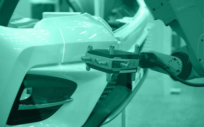
Dimensionally accurate components are essential for reliable assembly processes and the proper functioning of automotive components. Even minor deviations in diameters, distances, contours or gap dimensions can affect downstream processing, fit or component functionality.
OCTUM develops customized machine vision systems for automated optical measurement in the automotive and automotive supplier industries. The systems inspect defined dimensions and geometric features without contact in 2D or 3D – directly within the production process or at a separate inspection station.

Any questions?
Get directly in touch with our
experts on +49 7062 91494-0
or write to us using our contact form
What Is Automated Optical Measurement?
In optical measurement, cameras, laser scanners or 3D sensors capture the relevant areas of a component. The machine vision software uses the acquired data to identify defined measuring points, edges, contours or height information and calculate the required dimensions.
The measured values are compared with defined nominal values and tolerances. The system can then transmit a pass/fail decision to the machine control, assign components to a tolerance class or provide measurement data for documentation and process analysis.
The achievable accuracy depends on the measurement task, field of view, component geometry, surface, positioning, sensor technology and environmental conditions.
Which Dimensions and Geometries Can Be Inspected Optically?
Diameters and Radii
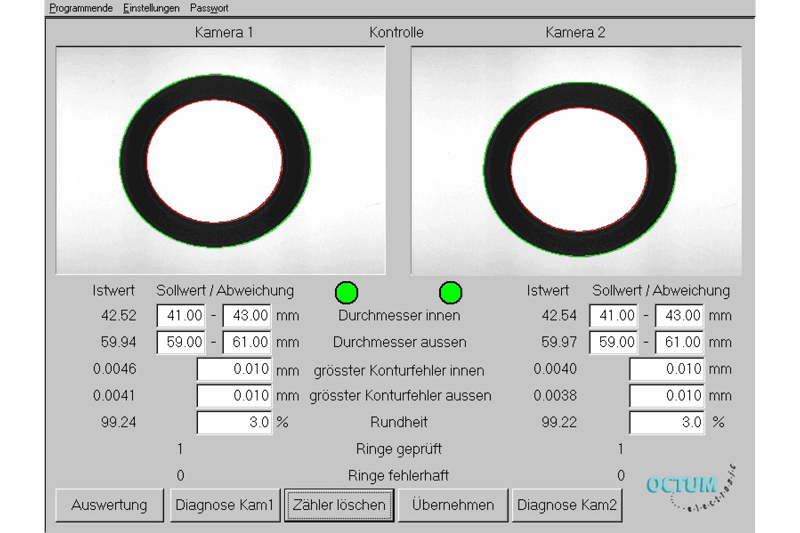
Inside and outside diameters as well as radii can be determined using defined component edges or contours and compared with the specified tolerances.
Lengths, Widths and Distances
Machine vision can measure lengths, widths, wall thicknesses and distances between edges, holes, recesses or other component features.
Angles and Positions
Angles, orientations and the relative positions of geometric features can be captured automatically. This makes it possible to determine, for example, whether holes, recesses or assembled components are positioned correctly.
Gap and Flush Dimensions
On assembled components or vehicle body parts, gap widths and height differences between adjacent surfaces can be inspected.
Contours and Profiles
Component contours can be compared with a reference geometry or defined tolerance limits, making local shape deviations detectable.
Heights, Depths and Volumes
3D methods can capture height profiles, recesses, raised areas and volume features for geometric evaluation.
Form and Positional Deviations
Depending on the measurement concept, characteristics such as roundness, flatness, parallelism, concentricity or the relative position of different component areas can be evaluated.
Which Automotive Components Can Be Measured?
OCTUM develops measurement solutions for a wide range of vehicle components and manufacturing processes, including:
- support rings, piston rings and other rotationally symmetrical components
- pistons, cylinder housings and crankcases
- indexable inserts and precision tools
- stamped, bent, turned and milled parts
- transmission and drivetrain components
- seals and sealing surfaces
- vehicle body and interior components
- plastic, metal and cast components
- assemblies with several relevant measurement features
- components with complex contours and free-form surfaces
The specific scope of measurement is defined based on the component drawing, specified tolerances, accessible component areas and installation conditions.
Optical 2D Measurement
In 2D measurement, features within a single image plane are evaluated. The method is particularly suitable for determining lengths, widths, diameters, distances, angles and contours when the relevant geometries can be imaged clearly.
High-contrast imaging of the measuring edges is essential. Depending on the component, front lighting, backlighting or a specially adapted lighting solution may be used.
Optical 3D Measurement
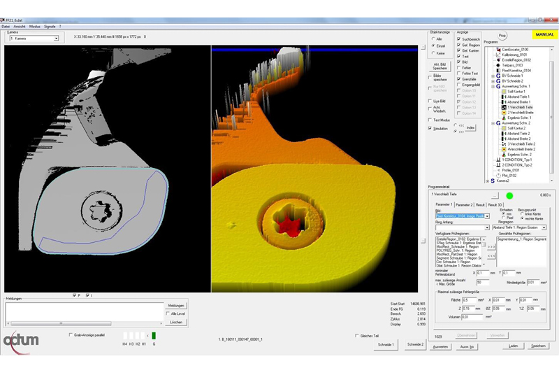
In addition to positions within the image plane, 3D methods also capture height information. This allows heights, depths, volumes, flatness, profiles and spatial shape deviations to be determined.
Possible methods include laser triangulation, stereo vision and other camera-based 3D imaging techniques. The appropriate method is selected based on the measurement range, accuracy requirements, surface properties and cycle time.
1. Capture and Align the Component
The component is captured in a defined position or while it is moving. Positional deviations can be detected within defined limits by the machine vision software and taken into account during measurement.
For rotationally symmetrical components or parts that must be inspected around their entire circumference, rotating units, rotary fixtures or multiple camera perspectives can be used.
4. Evaluate Tolerances and Transfer the Results
The measured values are compared with the stored nominal values and tolerance limits. The result can be transmitted to the machine control or a higher-level production system as a pass/fail decision or as a detailed measurement data set.
Depending on the system concept, measured values, images and inspection results can also be documented and statistically evaluated.
Typical Applications in Automotive Production
OCTUM develops solutions for measurement tasks including:
- diameter inspection of support rings
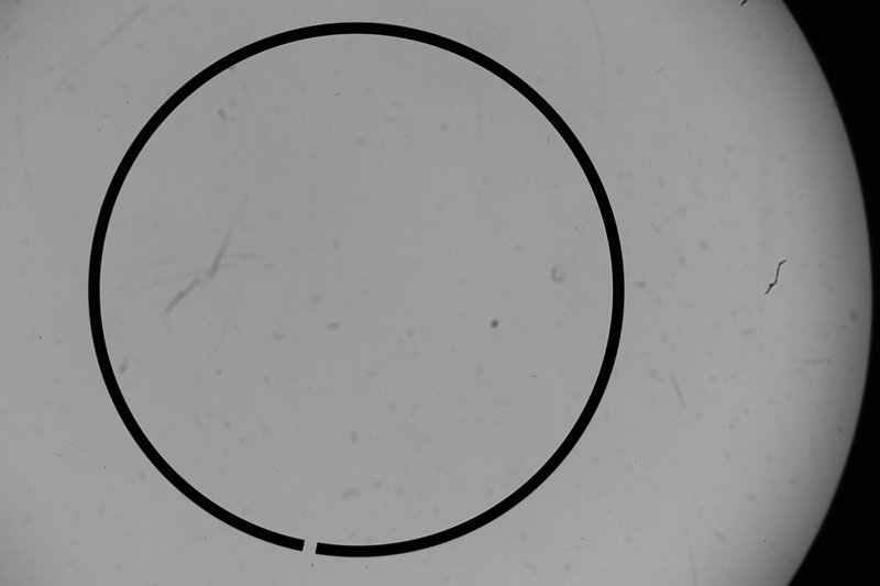
- measurement of piston ring end gaps
- geometry inspection of indexable inserts
- 3D volume measurement of automotive pistons
- inspection of inside and outside diameters
- measurement of lengths, widths and distances
- inspection of hole positions and distances between holes
- gap and flush measurement
- measurement of contours and profiles
- measurement of heights, depths and flatness
- inspection of the positions of assembled components
- comparison of measured contours with reference geometries
Whether a feature can be measured optically under the specified production conditions should be evaluated using original components, drawings and the required tolerances.
Which Factors Influence Measurement Accuracy?
The achievable measurement accuracy cannot be determined solely from the resolution of a camera or sensor. The interaction of the complete measurement system is decisive.
Important influencing factors include:
- size of the field of view
- required tolerances and measurement uncertainty
- camera and sensor resolution
- optics and magnification
- lighting and edge representation
- component surface and reflective properties
- component positioning and movement
- mechanical stability of the inspection station
- calibration of the measurement system
- temperature, vibrations and ambient light
- cycle time and available image acquisition time
For this reason, every measurement concept is adapted to the specific measurement task and production conditions.
The Difference Between Optical Measurement and Surface Inspection
Optical measurement determines defined geometric characteristics such as diameters, distances, angles, contours or heights and compares them with specified tolerances.
Surface inspection, by contrast, searches for local defects or deviations such as scratches, pores, cavities, coating defects or contamination.
Both inspection tasks can be combined within a single machine vision system when dimensional accuracy and surface quality must be inspected.
Detect Dimensional Deviations Early in the Process
If dimensional deviations are not detected until final inspection or assembly, additional processing steps have often already been completed, resulting in avoidable costs.
Inline measurement makes it possible to inspect defined dimensions immediately after a relevant manufacturing step. Nonconforming components can be specifically rejected, classified or transferred for rework.
Automated optical measurement supports:
- objective and repeatable dimensional inspection
- non-contact inspection of sensitive components
- inspection of every component passing through the designated measurement station
- early detection of dimensional and process deviations
- reduction of unnecessary downstream processing
- automated sorting by tolerance class
- documentation and statistical evaluation of measured values
- short inspection times within automated production processes
Integration into New and Existing Production Systems
OCTUM adapts the measurement system to the specific production environment. Relevant factors include cycle time, available installation space, component handling, measurement range, required tolerances and existing interfaces.
Depending on the application, different system concepts are possible:
- inline measurement within the production cycle
- offline or at-line measurement stations
- inspection of stationary or moving components
- use of multiple cameras or 3D sensors
- robot-assisted measurement
- rotating units for rotationally symmetrical components
- automated component feeding and positioning
- integration into new machines and production lines
- retrofitting of existing production systems
- communication with PLCs and machine controls
- transfer of measured values to higher-level systems
- format- and variant-specific measurement programs
From the Feasibility Study to Commissioning
The development of an optical measurement solution begins with the definition of the relevant measurement features, nominal values and tolerances. Ideally, component drawings, original parts and information about the intended production conditions are provided for this purpose.
As part of a feasibility study, OCTUM can investigate which optical method can capture the required features reproducibly. The results provide the basis for selecting cameras, sensors, optics, lighting, mechanical design and evaluation software.
OCTUM supports the project from concept development and implementation through integration and commissioning to ongoing support during operation.
Which Dimensions Can Be Inspected Using Machine Vision?
Depending on the application, machine vision can determine lengths, widths, diameters, radii, distances, angles, contours, gap dimensions, heights, depths and volume features. Which dimensions can be captured depends on the component geometry and optical accessibility.
What Is the Difference Between 2D and 3D Measurement?
A 2D measurement determines features within a single image plane, such as lengths, diameters, distances or angles. A 3D measurement additionally captures height information and is suitable for inspecting profiles, recesses, flatness and spatial shape deviations.
How Accurate Is Optical Measurement?
The achievable accuracy depends on factors including the measurement range, required tolerance, sensor resolution, optics, lighting, component positioning and environmental conditions. It must therefore be determined and verified individually for each measurement task.
Can an Optical Measurement System Inspect Multiple Features Simultaneously?
Yes. Multiple dimensions and geometric features can be determined within a single image or inspection station, provided they are optically accessible and can be captured with sufficient accuracy using the selected measurement setup.
Can an Optical Measurement System Be Retrofitted?
Retrofitting is generally possible. Factors such as the available installation space, component handling, cycle time, required measurement accuracy and existing machine interfaces must be evaluated.
What Is the Difference Between Optical Measurement and Surface Inspection?
Optical measurement determines defined dimensions and geometric properties of a component. Surface inspection detects local defects or deviations on the surface. Both inspection tasks can be combined within a single inspection system.
Is Your Measurement Task Not Listed?
Components, tolerances and production conditions differ from one application to another. Together with you, we evaluate how the relevant dimensions and geometries can be captured optically and how the measurement system can be integrated into your production process.
Talk to us about your components and measurement requirements.