




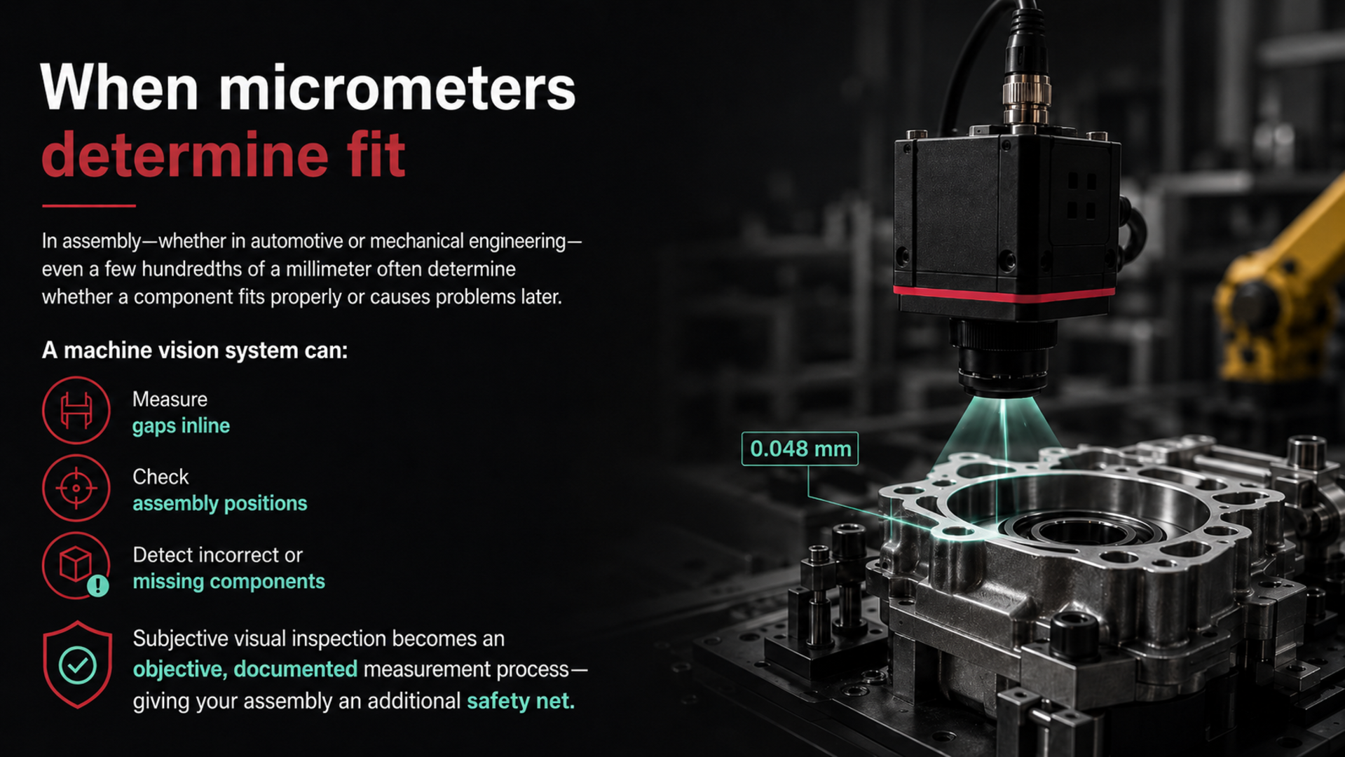
In industrial assembly, even minor geometric deviations can determine whether a component is seated correctly, functions reliably and meets the specified quality requirements. Particularly in automotive and mechanical engineering environments, just a few hundredths of a millimeter can affect fit, cause assembly problems or contribute to later functional failures.
Automated machine vision systems make it possible to detect such deviations directly during the assembly process. Gap dimensions, positions, distances and the presence of individual components can be inspected and documented without physical contact. This turns a subjective visual check into an objective, reproducible measurement process.
Small Deviation, Major Impact
Many assemblies consist of several individual parts that must be precisely aligned and assembled. Even minor deviations can cause components to tilt, fail to engage completely or sit outside the specified tolerances.
Possible consequences include:
- restricted assembly functionality,
- increased wear,
- leaks or unwanted noise,
- more difficult downstream processing,
- problems in subsequent assembly steps,
- scrap and rework,
- and customer complaints.
Especially in high-volume production, it is therefore important to inspect geometric features not only on a sample basis, but as comprehensively as possible during the running process.
Measuring Gap Dimensions Inline
Gap dimensions are an important quality characteristic in many assembly applications. They can indicate whether two components are positioned correctly relative to one another, whether a housing is fully closed or whether a component is seated evenly in its mount.
A machine vision system can detect defined edges and contours and calculate the distance between them. Depending on the application, individual measurement points or complete gap profiles can be evaluated.
Features that can be inspected include:
- gap width,
- uniformity of the gap profile,
- parallelism of component edges,
- distance between components,
- protrusion or offset,
- and deviations from defined target positions.
The results are compared with stored tolerance limits. If a measured value lies outside the permitted range, the component can be automatically marked, rejected or sent for secondary inspection.
Reliably Checking Assembly Positions
The mere presence of a component is not always sufficient. A component may be present but still be incorrectly positioned, rotated or incompletely assembled.
Typical inspection features include:
- position and orientation of a component,
- insertion depth,
- angular position,
- distance from reference points,
- centering within a mount,
- correct seating of clips, seals or fastening elements,
- and the position of moving components.
Automated position inspection makes it possible to verify immediately after assembly whether the component is within the permitted tolerances. This allows defects to be identified before the assembly reaches the next process step.
Detecting Missing or Incorrect Components
In addition to geometric deviations, incomplete assemblies or incorrectly fitted parts are common sources of errors in assembly processes.
An inspection system can verify whether all required components are present and whether the correct variant has been installed. These may include:
- screws, clips or retaining rings,
- seals and O-rings,
- plugs and contacts,
- springs or retaining elements,
- covers and housing parts,
- and variant-specific components.
Features such as color, shape, contour, marking or position can also be used to distinguish between different component variants.
This makes it possible not only to detect missing parts, but also to identify whether the wrong component has been installed or a part has been inserted in the wrong orientation.
Objective Inspection Instead of Subjective Visual Assessment
Manual visual inspections are still common in many production environments. However, they can be influenced by individual judgment, fatigue, time pressure or poor viewing conditions.
Visual assessment quickly reaches its limits, particularly with very small geometric deviations. A gap may appear uniform to the human eye while still lying outside the specified tolerance.
An automated machine vision system, by contrast, evaluates every product according to the same criteria. Inspection features, measurement ranges and tolerances are clearly defined. This creates a reproducible process whose results remain comparable regardless of shift, operator or production volume.
Automated inspection does not necessarily replace every manual check. However, it provides a reliable basis for consistent evaluation and relieves employees of repetitive inspection tasks.
Non-Contact Measurement at Production Speed
Optical inspection systems operate without physical contact. This is especially beneficial for sensitive surfaces, small components and high-speed production processes.
The inspection can be integrated directly into the assembly line. As soon as the component reaches the defined inspection position, one or more images are captured. The software evaluates the relevant features and transfers the result to the machine control system.
The process typically includes:
- Detecting or positioning the assembly
- Triggering image acquisition
- Capturing the relevant views
- Evaluating contours, positions and distances
- Comparing the results with the specified tolerances
- Transferring the inspection result to the PLC
- Rejecting or releasing the component
The entire inspection is carried out within the available cycle time without unnecessarily interrupting the production flow.
Stable Image Acquisition as a Prerequisite
To detect and measure small deviations reliably, the image acquisition conditions must be designed accordingly. High camera resolution alone is not sufficient.
The decisive factor is the interaction between:
- camera,
- optics,
- lighting,
- component positioning,
- mechanical stability,
- image processing software,
- and calibration.
The lighting must make relevant edges and contours clearly visible. Reflections, shadows or changing surfaces can influence the measurement and must therefore be considered during system design.
The position of the component also plays an important role. If its position varies too much, this must either be mechanically limited or compensated for by the software. Stable acquisition conditions are particularly critical when very tight tolerances are involved.
Measurement Results Must Fit the Application
The achievable measurement accuracy always depends on the specific application. Influencing factors include the field of view, camera resolution, optics, component geometry, surface characteristics and process stability.
A geometry inspection should therefore not be designed solely on the basis of theoretical pixel values. The key question is whether the required tolerance can be checked stably and reproducibly under real production conditions.
Before implementation, the following questions must be clarified:
- Which feature needs to be measured?
- Which tolerance limits apply?
- How large is the component?
- Which variants must be inspected?
- How stable is the product position?
- Which surfaces and materials are involved?
- What cycle time is available?
- How should borderline cases be handled?
For particularly demanding applications, a feasibility study may be advisable. This determines whether the relevant features are sufficiently visible optically and can be measured with the required level of stability.
Multiple Perspectives for Complex Assemblies
Not all inspection features are visible from a single camera perspective. Additional cameras may be required for complex geometries, concealed components or multiple assembly levels.
Depending on the task, the following views can be combined:
- top views,
- side views,
- oblique views,
- internal views,
- or rotating views.
The results from the individual cameras are combined into a single inspection decision. This allows an assembly to be assessed comprehensively without having to rotate it manually or inspect it several times in separate steps.
Documenting and Evaluating Inspection Results
A major advantage of automated inspection systems is the ability to store inspection results and link them with other production data.
Depending on the application, the following information can be documented:
- individual measurement values,
- pass/fail results,
- defect type and defect position,
- timestamps,
- product or serial number,
- batch and production order,
- inspection program used,
- and selected inspection or defect images.
These data support more than just traceability. They can also be used to identify trends in the production process at an early stage.
If a gap dimension gradually changes over an extended period, for example, this may indicate tool wear, mechanical changes or declining process stability. Machine vision therefore becomes not only an inspection system, but also a source of information for process optimization and preventive maintenance.
Integration into the Machine and Quality Process
Reliable inline inspection requires more than a camera and a measurement algorithm. The system must be fully integrated into the machine and production process.
This includes:
- suitable installation positions,
- coordinated trigger signals,
- clearly defined interfaces to the PLC,
- unambiguous product tracking,
- defined rejection mechanisms,
- suitable operating and user concepts,
- and the transfer of relevant inspection data.
OCTUM therefore considers machine vision in the context of the machine, product, process and quality objective. Camera, optics, lighting, software and interfaces are designed as one integrated system.
Early involvement in machine planning is particularly beneficial for geometric measurement tasks. This allows stable inspection positions, suitable lines of sight and the necessary installation space to be considered from the outset.
An Additional Safety Net for Assembly
Inline geometry inspection adds another layer of control directly within the production process. Defective assemblies are detected before further components are installed or additional value-adding steps are carried out.
This reduces the risk of defective products passing unnoticed into downstream processes. At the same time, rework, scrap and later customer complaints can be reduced.
A suitable machine vision solution supports several objectives at once:
- objective evaluation of quality features,
- comprehensive inspection at production speed,
- early detection of assembly deviations,
- documented measurement values,
- improved traceability,
- and greater transparency regarding process stability.
When just a few hundredths of a millimeter determine whether a component fits correctly, optical inspection becomes an important part of assembly quality.
Because a reliable inspection solution does not merely detect whether a component is present. It verifies whether it is actually seated correctly.